Vericut CNC multi-axis machining simulation software
- Handiso Selamu Yisihak (Ph.D. .Ing. and Edu.) (韩士兰)

- Sep 25, 2022
- 4 min read

Function introduction
Vericut is a research and development company of CGTECH, headquartered in Irvine, California, USA. , virtual simulation software for process program optimization.
Vericut software was introduced to the market in 1988 and has more than 20,000 customers and more than 1 million users worldwide. The software is widely used in aviation, aerospace, weapons, ships, medical, automobiles, molds, and other major manufacturing industries.
feature of product
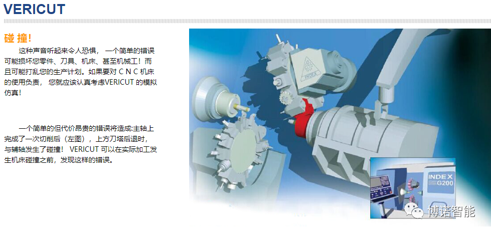
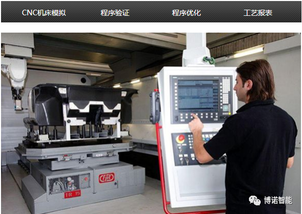
1. CNC Machine Simulation
A machine tool crash is expensive, not only potentially destroying the machine, but also delaying the entire production schedule! But using it can significantly reduce the chance of error and avoid spending valuable machining time trying to cut new programs on the actual machine. Machine tool simulation can detect collisions and collisions between all machine tool components such as axis slides, spindle heads, turrets, rotary tables, spindles, tool changers, fixtures, cutting tools, and other user-configured machine accessories. critical collision. Users can set a critical collision zone around the part and detect surrounding critical collision states and overtravel errors. The simulation of machine tool movements in VERICUT's inspection mode can even be performed in a step-by-step or rewind mode. Users can select a machine from the machine library, modify and customize it, or rebuild their own machine model. Users can design machine parts in a CAD system or define machine parts. The "component tree" function can easily connect components and manage machine kinematics.

2. CNC program verification

AUTO-DIFF compares the design model to VERICUT's "cut" model, allowing you to detect gouges and residual material.
When ready for cutting work, the product design may have gone through several engineers/programmers, departments, companies, and CAD/CAM systems. Finally, it is difficult to suggest from the toolpath file whether it accurately reflects the design intent. With AUTO DIFF, you can be sure. Design models may be solids, surfaces, skins, shells, or points. You can "embed" it in the blank as an interactive gouge check. VERICUT highlights gouges and logs errors if the tool cuts into the design model.
For easy identification, you can assign different colors to the design model, stock, error display, gouge, collision, or residual material. Using the Export Model module, you can export the comparison results to a surface model in IGES format.
Included Analysis Tools With the Basic Verification module, you can analyze and view machined workpiece geometries. The model can be sectioned multiple times in any direction, so you can view areas that are impossible to observe in a solid model (such as a section of a borehole). The X-Caliper tool can measure thickness, volume, depth, clearance, distance, angle, hole diameter, tapped features, chamfers, rest heights, and edges. The X, Y, and Z axis coordinates can also be measured. With X-Caliper you can selectively emphasize features, such as planes at the same level. You can view and measure all tool interferences, even if subsequent machining has removed them from the screen.
3. CNC program optimization

Optimization principle
When cutting a large amount of material, the tool feed rate is reduced; when cutting a small amount of material, the feed rate is correspondingly increased. Depending on the amount of material removed per cutting step, the optimization module can automatically calculate and insert improved feed rates where needed. Without changing the program trajectory, the optimization module creates a new CNC program by updating the cutting speed of the original program.

more efficient
In the same amount of time, more parts can be machined - it's like adding a CNC machine. Shorten the production cycle, improve production efficiency, and bring products to market faster.
save money
Significant annual savings can be achieved by reducing part-processing time and increasing productivity.
Improve part quality
The stable cutting resistance ensures that the tool does not deform or the deformation is small. Parts have a higher surface finish in corners, edges, and transition areas with minimal fitter work.
Extend tool life
Optimal cutting conditions extend tool life. Shorter machining times mean less tool wear, so there is no need to change tools as often.
Reduce machine wear
The more stable cutting resistance between the machine tool and the workpiece reduces the variable load of the shaft motor and makes the operation more stable.
better use of time
Operators are not tied to excessive feed rates. They can operate multiple machines, prepare for the next job, or do other things.
4. CNC process report
Generate process inspection instructions and documentation to save time and improve accuracy based on process tooling characteristics generated by VERICUT simulations.
VERICUT automatically creates inspection instructions and complete cutting process feature dimensions. This helps to establish a formal, simple, and efficient method for creating and documenting inspection protocols. Inspection reports can be. This makes it quick and easy to create inspection sequence descriptions, as a process model is used to graphically select the features to inspect. EXTRACTING FEATURES VERICUT identifies features and sizes and applies standard tolerances to measurements. You can also add any additional notes and select the measuring instrument from the list. When the inspection sequence is complete, the inspection report (like other VERICUT reports) can be saved in standard HTML or PDF format.

With VERICUT, you can:
● Avoid machine collision
● Eliminate part trial cutting ● Shorten the production cycle
● Increase tool life ● Increase CNC productivity
● Enhance competitiveness

https://mp.weixin.qq.com/s/uhdH25waEHoKkc4_FIuPRw


Comments